Preservation of Covered Bridges
This page lists the various types of trusses listed in the World Guide to Covered Bridges.
In the 1960’s, Ray E. Wilson (1892-1975), a mechanical engineer, researched covered bridge trusses and prepared the descriptions used in previous editions of the World Guide to Covered Bridges. In recent years, there has been renewed interest in researching the history of specific bridges, builders and truss designs. This research continues to improve World Guide listings by determining more accurate construction dates and refining truss descriptions. It has also prompted us to expand this section discussing the various types of trusses. Research since the prior edition of this Guide scrutinized some long-standing labels that have been applied to certain bridges. Specific examples include structures in New Hampshire formerly listed as Long trusses that, upon closer examination and comparison with the intent of the patented design, were found not to contain integral parts of that design. Also, some bridges in Ohio previously listed as Warren trusses are now considered to be a Smith truss variant. The following descriptions and line sketches show simplified versions of the most usual arrangement of the various types of trusses found in existing covered bridges and do not necessarily agree with the patented designs. Timbers are shown by full lines, and iron or steel rods by dotted lines. There are many examples of variations, modifications, and refinements to these truss designs introduced by local builders or, in some cases, modifications made by builders to avoid paying royalties on a patented design.
| King | Dating to the Middle Ages, the kingpost is the oldest and simplest bridge truss design. It is based on the inherently stable form of an equilateral triangle. The kingpost truss is essentially a triangle with a central post, known as the kingpost. The two diagonal timbers are braced on the ends of lower chord and function in compression, transmitting loads from the center of the bridge back to the abutments. |
|
| Queenpost | The queenpost truss system followed the kingpost chronologically and dates back at least to the Italian Renaissance. The queenpost truss is really an expansion of the kingpost design because of an additional rectangular panel placed in the center between the two triangles that originally faced the central kingpost timber. As the span of a queenpost truss is increased, the distance between the bottom chord panel points also increases. At some point the progressively longer bottom chords start to sag from the loads. The queenpost truss is often reinforced by placing vertical and diagonal timbers or rods in the open center panel (shown by the dashed lines) to obtain greater strength for the longer spans. It was typically used to span distances up to 75 feet. |
|
| Multiple Kingpost | The multiple kingpost design was developed to span longer distances, frequently up to one hundred feet. The design consists of one kingpost in the center with several right angle panels on each side of the center. The multiple kingpost truss was able to span moderate crossings, occasionally exceeding one hundred feet. Most of these trusses were built with an even number of panels so that all the diagonals are in compression and all the verticals are in tension except at the ends of the truss under normal loading. With an odd number of panels, the center panel may be open or have crossed braces as shown by the dashed lines in the lower image. |
|
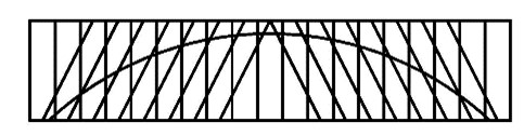
| Burr | Theodore Burr (1771-1822) was an inventor from Torrington, Connecticut. He patented his first bridge design in 1806 and was awarded another patent on April 4, 1817 for his arch and truss bridge design. The 1817 patent drawing shows a multiple kingpost truss resting on stone abutments, superimposed with an arch whose ends are seated against the abutments below the lower chords. The usual Burr truss has two arches (sometimes four) with a multiple kingpost truss sandwiched in between. These arches may be of hewn or sawn timbers. The kingposts are sometimes flared out at the top and the bottom, and may be plumb or normal to the curve of the arch or arches. The design became quite popular and thousands of covered bridges were built with Burr truss designs. Today, about one-quarter of the remaining historic covered bridges use this design. with |
|
| Town Lattice | Although Ithiel Town (1784–1844) is primarily recognized as an architect, he made a significant contribution to the field of engineering when, in 1820, he was granted a patent for a truss bridge consisting of two layers of overlapping planks running perpendicular to each other, with each layer arranged at an angle to the chords, forming a lattice fastened together with wooden pins or treenails at each intersection. The most significant feature of this design was that it could be quickly erected utilizing sawn planks instead of heavy hewn timbers. As Town explained, his method of bridge construction was designed to be "the most simple, permanent, and economical, both in erecting and repairing." Québec employs a variation of the design and some railroad bridges had double lattices to carry the heavier loads. |
|
| Long | Col. Stephen Harriman Long (1784–1864) attended Dartmouth College, taught mathematics at West Point, and became an army engineer in 1814. He undertook numerous surveys for the U.S. Army Topographical Engineers of canals and led expeditions in the West. As a consulting engineer for the Baltimore & Ohio Railroad, Long became interested in the design and construction of bridges. In 1830 he obtained a patent for a wooden truss bridge with diagonal compression members, vertical tension members and diagonal counterbraces. He received patents for variations on this design in 1836 and 1839. Central to Long's patented design was the concept of driving wedges between the counterbraces and chords, which prestressed the structure, and added substantially to its carrying capacity. |
|
| Howe | The Howe truss, patented by Massachusetts millwright William Howe in 1840, includes vertical iron or steel tension rods and diagonal wooden braces and counterbraces crossing within each panel. By substituting adjustable iron rods for the wooden posts of the Long truss (1830), Howe overcame the inherent difficulty of creating tension connections in wood and simplified the process of erecting and repairing bridges. It was used extensively in the United States and Europe and was especially well suited for railroad bridges. In 1878, the American Society of Civil Engineers called it "the most perfect wooden bridge ever built.”
Most bridges in the eastern and midwestern United States have two diagonal braces and one counterbrace in each panel and two vertical rods between, but the end panels often have three rods. The Howe trusses in the western United States tend to have a pair of diagonal braces in each panel angled towards the center of the bridge and two or more panel rods. The center panel often has crossed diagonals although occasionally, the center panel does not have any diagonal braces. Adaptations of the design are also found in New Brunswick. Howe trusses were popular in parts of Europe where some still stand in Austria, Germany and Switzerland. |
|
| Paddleford | Peter Paddleford (1785–1859) of Littleton, New Hampshire, was a prominent nineteenth-century millwright and bridge builder in northern New England. Initially, Paddleford used the 1830 Long truss for his bridges, but soon developed his own design with long counterbraces extended over more than one panel, which helped distribute loads and increase the truss's rigidity. Although Paddleford never patented the design, it dominated covered bridge construction throughout northern New England for over half a century. Examples of this design are found in northeastern Vermont, northern New Hampshire and northwestern Maine. Some Paddleford truss bridges also include arches which may have been added later for additional support./td> |
|
| Smith | Robert W. Smith (1834–1898) was the son of an Ohio cabinet maker. On July 16, 1867, he received a patent for a design with compression members at 45 degrees and tension members at 65 degrees. His goal was to reduce the amount of timber in the structure. He moved to Toledo, Ohio that year and organized the R.W. Smith & Company partnership. Smith received a second bridge patent in 1869 for roofing and lateral-bracing systems. He continued to modify and refine his designs but did not apply for additional patents. As a result, many Smith truss bridges do not exactly follow the patented designs. In 1870, the company's name was changed to Smith Bridge Company. Over time the company transitioned to the exclusive fabrication of metal bridges. The variety of Smith trusses makes categorizing them somewhat challenging. Research into the topic has generated a revision to the descriptions previously used. These revised descriptions are intended to follow the designs and drawings used by Smith when promoting his bridges. Single web – this design resembles a series of inverted Vs. These structures were incorrectly identified as Warren trusses in previous editions. Three examples remain in Ohio. Double web – there are two styles of the double web design. The second web was a copy of the first although the truss started at a different location within the pattern. Formerly referred to as Type 3. Type A (symmetrical) – the second web is placed such that the tension members from one web are halfway between those of the other web giving the appearance of Xs. Type B (asymmetrical) – this is seen as continuous Xs, but a close inspection will show that the tension members are not symmetrical, that there is one more towards one end than the other. Triple web – a third web added for additional strength in longer spans. The design of the third web is a duplicate of the first. Formerly referred to as Type 4 |
Smith Single Smith Double |
| Pratt | The Pratt truss was originally patented by Thomas and Caleb Pratt in 1844. In its earliest form, the Pratt truss was a combination wood and iron truss. The top chord and verticals acted in compression and were made of wood, while the bottom chord and diagonal members acted in tension and were made of iron. This combination Pratt truss was built through the 19th century and as late as 1908. All-metal examples of this design were built well into the 20th century. Teco-Pratt designs usually have triple timbers. The California design has wooden posts and 2 iron rods as diagonals, crossed in center panel. |
|
| Childs | Horace Childs (1807–1900) had first-hand experience with construction of the Long truss as an agent for his mother’s cousin Col. Stephen Long. He conceived his own truss to correct "defects" in Long’s design by substituting iron rods for his cousin’s counterbraces. He received a patent on August 12, 1846. In his design, the diagonals are mortised to chords. The only existing covered bridges using this design are in Ohio’s Delaware and Preble counties. |
|
| Partridge | The Partridge truss was designed and patented in 1872 by Reuben Partridge (1823–1900) despite its similarities to a Smith patent. It was limited to central Ohio in the late 1800's and early 1900's, and the only existing covered bridges using this design are in Ohio’s Franklin and Union counties. These surviving examples are modified designs with reinforcing rods and additional timber diagonals. |
|
| Brown | Josiah Brown, Jr. of Buffalo, New York patented the Brown truss on July 7, 1857 as US patent 17,722. Little is known about Brown’s life. According to census records, he was born in New York around 1820 and was living in Kent County, Michigan by 1860. His is listed as a bridge builder in Holland’s 1868 East Saginaw Michigan City Directory with an office at the corner of Washington and Genesee. Brown truss bridges are only known to have been built in Michigan and only one historic bridge of this type survives in Fallasburg, Michigan. |
|
| McCallum | Daniel Craig McCallum (1815–1878) was born in Scotland and immigrated to America as a child. McCallum began his career with the New York & Erie Railroad, and in 1848, was put in charge of building bridges. After conducting experiments on wood truss models, McCallum devised a new type of truss with an arched upper chord and prestressed counterbraces. Combining the arch and truss, he claimed, would "render their united strength available at the same time...and preserve it at a time when any other bridge would fail." McCallum took out patents in 1851 and 1857 for his "Inflexible Arch Truss." By 1860, the McCallum truss was in use on railroad lines across North America. His truss gradually fell out of favor because it was difficult to frame. By 1870, the McCallum truss was obsolete. There is one surviving example in Québec. |
|
| Haupt | Herman Haupt (1817–1905) was a major figure in the development of American railroads and bridge building. He entered the military academy at West Point, New York at age 14 graduating with an engineering degree in 1835. While overseeing construction of the York & Wrightsville Railroad, his concern that the bridges might not handle the heavy loads prompted him to begin modeling and testing designs which led to an "improved lattice truss." The patent was for a horizontal chord truss with vertical posts and multiple-intersection diagonal braces, combined with a full-length kingpost truss. Few Haupt patent truss bridges were ever built due to their complex design. In 1851, he published his General Theory of Bridge Construction, which became a standard textbook in engineering schools across the country. There is one remaining example: the Bunker Hill Bridge in Catawba County, North Carolina. |
|
| Arch, tied (shown), or two hinged (not illustrated) | The arch is sometimes used alone in place of a truss, with vertical, diagonal, or crossed suspension rods in each panel, as indicated, to carry the load from the floor to the arch. The drawing indicates various arrangements of suspension: verticals, diagonals, and crossed X bracing. |
|
| Suspension or Bowstring | The Germantown Bridge is a rare example of a "rigid suspension truss bridge" in which all compression members are of wood and the main tension member is an inverted chain of iron eye bars. Builder David H. Morrison (1817–1882) also developed several other types of bridges during his career. |
|
| Unique Trusses | There are numerous structures whose trusses do not conveniently fit into any particular category. One example, pictured here, represents the design used in two similar bridges: Sayres Bridge in Orange County, Vermont, and the Bath Village Bridge in Grafton County, New Hampshire. |
 |